
Remember me
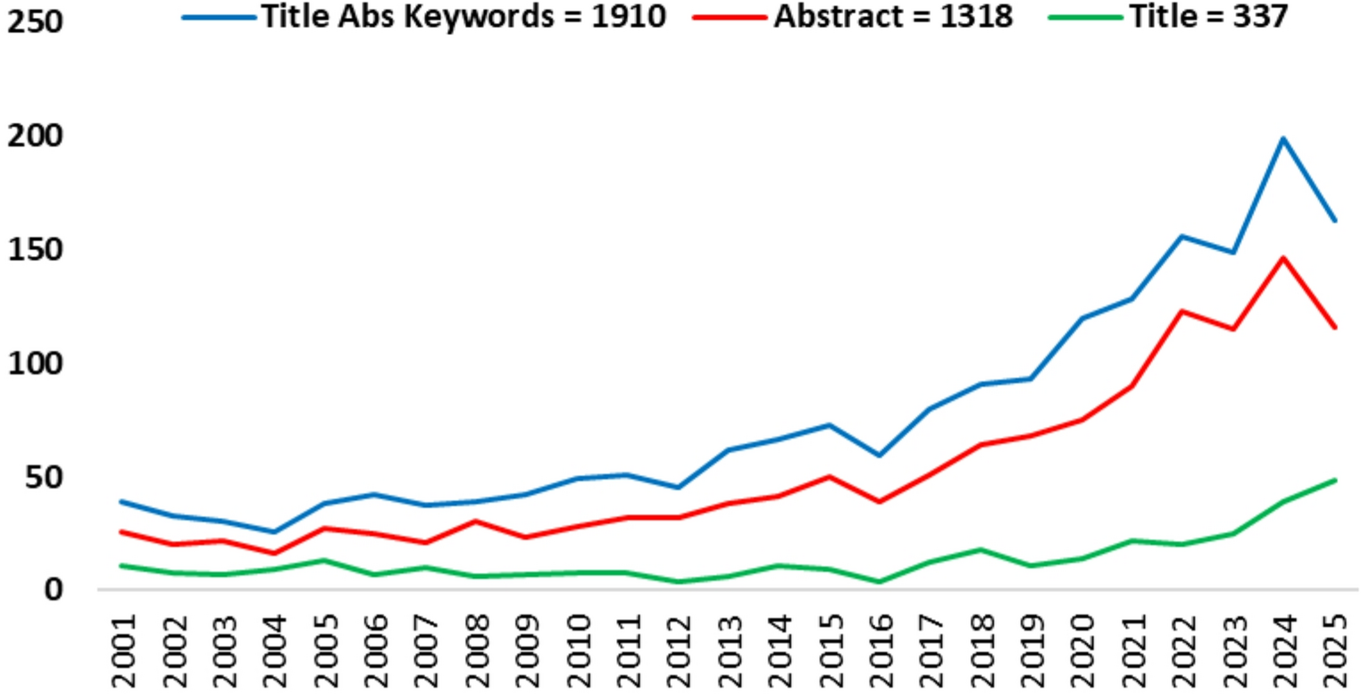
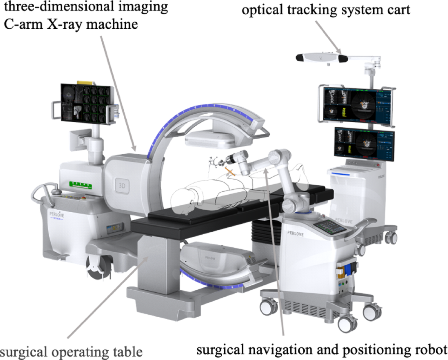


The new spinal surgical robot system consists of a three-dimensional imaging C-arm X-ray machine, an optical tracking system cart, and a surgical navigation and positioning robot (Fig. 1). It integrates intraoperative three-dimensional imaging, navigation positioning, and surgical planning functionalities. The spinal surgical robot system employed in this study, named the Perlove Spinal Surgical Robot, was collaboratively developed by our research team and Perlove Medical.
Fig. 1
The components of the new spinal surgical robot system comprise a three-dimensional imaging C-arm X-ray machine, an optical tracking system cart, and a surgical navigation and positioning robot
Optical tracker registration methodFigure 2 shows the optical tracker for the 3D C-arm. This study employed a new automatic registration method integrated into the spinal surgical robot system. The method relies on an optical tracker rigidly mounted on the detector of the 3D C-arm. During intraoperative 3D imaging, the navigation system tracks the C-arm’s position and orientation in real-time. Immediately following image acquisition, the reconstructed 3D dataset and its spatial coordinates are automatically transmitted to the robot, thereby achieving instantaneous registration between the image space and the robotic surgical space.
Fig. 2
Integration of the optical tracker with the 3D C-arm. (A) An optical tracker is rigidly mounted on the detector of the 3D C-arm, shown here in its pre-planned initial scanning position. (B–D) During 3D image acquisition, the C-arm rotates continuously along a predefined arcuate trajectory (indicated by the red arrow). This motion trajectory is captured in real-time by the optical navigation system and serves as the foundational input for the subsequent trajectory-based, markerless spatial registration algorithm
High-precision lateral force sensing system methodFigure 3 shows the high-precision lateral force sensing system integrated into the robotic end effector. During the surgeon’s K-wire implantation procedure, the optical tracking system cart screen displays real-time deviations between the actual K-wire insertion path and the preoperatively planned path. The “skiving” phenomenon, where a K-wire slides along a non-perpendicular or irregular cortical surface, is a primary cause of trajectory deviation during surgical insertion. This issue is magnified in percutaneous spine procedures due to lateral forces from soft tissue tension and the often-inclined surfaces of pedicle entry points. Conventional methods and standard robotic systems lack the ability to perceive these subtle mechanical disturbances, leading to repeated attempts, prolonged procedures, and an increased risk of iatrogenic injury to critical structures like nerve roots. To address this, our system incorporates a high-precision 3D lateral force sensor within the end-effector. This module monitors real-time shear forces and moments on the K-wire, synchronizing this data with the navigation software. When anomalous lateral forces indicative of skiving is detected, the system generates color-coded visual alerts and displays quantitative deviations (entry, tip, and angular errors) on the navigation screen. This actionable feedback enables the surgeon to make immediate corrective adjustments, thus preventing trajectory deviation and ensuring accurate K-wire placement.
Fig. 3
High-precision lateral force sensing system and its navigation interface feedback. (A) The robotic end-effector is equipped with a six-axis force/torque sensor for real-time detection of forces on the K-wire during insertion. (B) The navigation software integrates force data with spatial tracking to visualize deviations between the actual and planned trajectories. (C) Display key accuracy metrics: entry point deviation (0.25 mm), tip-to-trajectory distance (0.24 mm), end point deviation (0.25 mm), and end point deviation along the instrument axis (0.57 mm)
Surgical workflow of the new robotic surgical systemThe key procedural workflow for robot-assisted K-wire placement in the new spinal surgical system comprises the following stages: (1) Image Acquisition Phase, (2) Image Processing and Registration Phase, (3) Surgical Planning Phase, (4) Robotic Positioning Phase, (5) Surgical Execution, and (6) Verification Phase (Fig. 4).
Fig. 4
The key procedural workflow for robot-assisted K-wire placement using the new spinal surgical system
Preoperative planningPrior to the surgical procedure, the navigation system was initialized by activating the device power supply and launching the operational software. Patient demographic data were registered, followed by the selection of three-dimensional image orientation parameters aligned with the patient’s decubitus position and C-arm configuration. Upon completion of 3D C-arm registration, patient data were synchronized to the optical tracking system cart. The navigation interface was subsequently initialized using optical tracking software. Three-dimensional image acquisition was then performed, with volumetric datasets automatically transferred from the C-arm workstation to the tracking cart for intraoperative navigation access.
Intra-operative robot registrationFollowing preoperative planning, the optical tracking system was deployed for trajectory planning of the K-wire. The optimal entry points and insertion depths were computationally determined using integrated planning software. The robotic manipulator cart was then positioned adjacent to the operative table. Spatial registration was achieved by acquiring the manipulator’s base tracer coordinates. Subsequent fiducial registration incorporated the robotic coordinates into the navigation space. Upon validation of targeting accuracy, the robotic arm executed autonomous positioning to preplanned coordinates, with final trajectory confirmation against intraoperative CT benchmarks.
Surgery implementationFollowing robotic positioning, a percutaneous stab incision was created along the planned trajectory using a trocar-tipped lancet. Through this access, a cannulated sleeve was deployed to the lamina surface. The K-wire was advanced into the vertebral body via a powered drill through the guiding sleeve. This procedure was iteratively performed for all predetermined trajectories. Upon completion, the robotic platform was retracted from the surgical field. Postimplantation verification was conducted using intraoperative 3D imaging with multiplanar reconstruction to assess the accuracy of K-wire placement.
Clinical data acquisitionAge, sex, BMI, Bone mineral density, average number of k-wires, and number of surgical segments were recorded. The number of punctures (NOP) is defined as the total number of percutaneous insertion attempts required to achieve successful implantation of a K-wire. The mean time required to insert a K-wire (MTRI K-wire) is defined as the average duration required for successful percutaneous implantation of a K-wire, measured from initial skin penetration to final radiographic confirmation of position. The average blood loss per K-wire insertion (ABL K-wire) is defined as the average volume of hemorrhage occurring during successful percutaneous implantation of a K-wire, quantified from initial skin penetration until final fixation. The fluoroscopy count per K-wire (FC K-wire) is defined as the number of radiographic exposures required to achieve successful percutaneous implantation of a K-wire. The puncture abduction angle (PAA) is defined as the angle between the K-wire trajectory and the midline of the vertebral body. The K-wire in the pedicle (K-wire IP) is defined as complete intraosseous positioning of the K-wire within both the pedicle and vertebral body boundaries, verified on postoperative CT reconstructions with no cortical breach observed in any plane.
K-wire accuracy assessmentA clear methodology for determining the entry and end point deviationsThe overall flowchart of the deviation calculation method is shown in Fig. 5. First, the deviation calculation method uses a preprocessing method, including image threshold segmentation and morphology, to segment the lumbar vertebrae in the three-dimensional C-arm CT planning image and postoperative C-arm CT image. The segmented lumbar vertebrae are then converted into point cloud form. Afterward, the iterative closest point registration method is used to achieve three-dimensional registration of the point cloud of the lumbar vertebra from the planning image and the postoperative image, resulting in the calculation of the registration deformation matrix. Then, this registration deformation matrix is then applied to the planned paths for pedicle screws to map it from the planning image space to the postoperative image space. The K-wires in postoperative C-arm CT images are segmented using the above preprocessing method. Finally, deviations in the entry points, end points, and angles of insertion between the mapped planned path and the actual implanted K-wires can be calculated in the same postoperative image space.
Fig. 5
Overall flowchart of the deviation calculation method
Detailed calculations or formulas used to quantify these deviationsThe i-th implanted K-wire and the corresponding planned path are shown in Fig. 6, where the planned path has been mapped from the planning image space to the postoperative image space. The entry and end points of the i-th implanted K-wire are pi,1 and pi,2, respectively, whereas the entry and end points of the corresponding planned path are \(\:_,1}^}\) and \(\:_,2}^}\), respectively. These formulas calculate a simple Euclidean distance between the two points.
Fig. 6
Illustration of the i-th implanted K-wire and the corresponding planned path in the postoperative image space. The red line denotes the implanted K-wire, and the green line denotes the corresponding planned path
The distance deviation d1 for the entry point between the i-th implanted K-wire and the corresponding planned path can be calculated using Formula (1) [12] as follows:
$$\:_=\sqrt_-_^}\right)}^+_-_^}\right)}^+_-_^}\right)}^}$$
(1)
Similarly, the distance deviation d2 for the endpoint between the i-th implanted K-wire and the corresponding planned path can be calculated using Formula (2) [13] as follows:
$$\:_=\sqrt_-_^}\right)}^+_-_^}\right)}^+_-_^}\right)}^}$$
(2)
The angle deviation α between the i-th implanted K-wire and the corresponding planned path can be calculated using Formula (3) [14] as follows:
$$\:\alpha\:=}^\frac__}\cdot\:\stackrel_^}_^}}}__}\right|\cdot\:\left|\stackrel_^}_^}}\right|}$$
(3)
Research designThis study is a retrospective study and was approved by the Ethics Committee. From December 2022 to April 2024, 127 patients who met the inclusion and exclusion criteria were implanted with K-wires using freehand fluoroscopy assistance or new spinal surgical robot assistance. All patients were fully aware of the possible risks of the operation and signed informed consent before the operation. All operations were performed by a senior deputy chief physician of spinal surgery at the Second Affiliated Hospital of Nanjing Medical University from December 2022 to April 2024. For the robot-assisted surgery group, a three-dimensional C-arm machine was used in conjunction with a new spinal surgical robot to obtain the patient’s anterior and lateral views and 3D images of the spine. The inclusion criteria were as follows: (1) Suitable for general anesthesia, with an American Society of Anesthesiologists (ASA) physical status classification of I, II, or III; (2) Diagnosed with vertebral compression fracture, spinal canal stenosis, or lumbar scoliosis requiring surgical intervention, as confirmed by radiological findings; (3) Provided written informed consent from the patient and/or their legal guardian to undergo robot-assisted percutaneous vertebroplasty (PVP) or percutaneous pedicle screw fixation (PPSF). The exclusion criteria were: (1) Severe or complex spinal deformities (e.g., Cobb angle > 40° or deformities requiring osteotomy); (2) Presence of spinal tumors, infections, or active tuberculosis; (3) History of previous surgery at the target spinal segments; (4) Spondylolisthesis of Meyerding grade II or higher; (5) Uncorrected coagulopathy or ongoing anticoagulation therapy; (6) Pregnancy or lactation; (7) Presence of severe, uncontrolled systemic diseases (e.g., severe cardiac, pulmonary, hepatic, or renal insufficiency). The participants retained the right to withdraw from the trial at any point without penalty. The study will be immediately discontinued per protocol-specified stopping rules upon the occurrence of serious adverse events.
Statistical analysisIndependent samples t tests and chi-square tests were employed to compare the baseline characteristics, imaging parameters, and clinical outcomes between the two cohorts. All of the statistical analyses and graph plotting were performed using SPSS 27.0 and Origin 2024. Statistical significance was defined as P < 0.05.
Comments (0)