
Remember me
An optical parametric oscillator (OPO) is a paradigmatic nonlinear photonic device, in which parametric down-conversion of pump photons produces signal and idler photons. Despite such a simple working mechanism, the range of functions that an OPO can fulfill is surprisingly broad. OPOs have long been used as coherent light sources, whose wavelength could be widely tuned by varying phase-matching conditions [1–3]. Leveraging the nonlinear behavior of the OPO, an optical power limiting function can be realized [4]. Beyond such classical functionalities, OPOs found multiple quantum use cases such as sources for entangled photon pairs [5], squeezed lasers [6], sensors for quantum statistics of weak signals [7, 8], and contributed to enhancing the sensitivity of gravitational-wave detectors [9]. Furthermore, multiple OPOs, when coupled together as a network, can realize emergent functions that a single OPO cannot achieve. Using each OPO as an emulator of an Ising spin, coherent Ising machines (CIMs) composed of an OPO network can solve combinatorial optimization problems [10, 11]. It has been shown that a network of OPOs can even constitute a Turing-complete computational system [12].
The functions of OPOs in these different roles is fundamentally connected to the specific geometry they are realized in. For instance, a free-space OPO with large, bulky, nonlinear elements enables handling high laser powers and tunable phase-matching conditions. In contrast, the confinement of light into narrow waveguides on photonic chips offer high local intensities, resulting in extremely low OPO thresholds, which are essential for delicate signal processing and for quantum photonics [13–15]. OPOs realized in long fiber-based loops or in race-track geometries can support thousands of modes, which are the key to the speed and the computation power of CIMs [10, 11], and other neuromorphic computing devices [16]. Even an OPO without mirrors has been demonstrated, realizing simple and reliable device operation [17]. Thus, the future exploration of novel functions of OPOs will be unavoidably tied to the conception of new, unique, geometries.
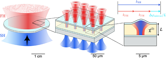
In this work, we propose a new design strategy for vertical micro-cavity OPOs (VCOPOs) based on integrated micro-optics, quantitatively analyze their performance, and discuss potential applications. As shown in figure 1, the proposed VCOPO is composed of a thin film of  nonlinear material, sandwiched between highly reflective dielectric mirrors. The pump and signal beams are coupled in and out using free-space focusing optics, and the phase-matching conditions are ensured by phase engineering of the dielectric mirrors, lifting the need for conventional techniques like birefringent phase-matching [18] or periodic poling [19]. As such, VCOPOs have several unique advantages compared to conventional geometries. First, the small footprint of each ‘cell’ and two-dimensional integrability could enable high scalability, while also maintaining high nonlinear efficiency. Second, the out-of-plane emission of light enables its efficient collection, offering advantages for quantum applications where loss is a critical limitation [20]. Lastly, thanks to the minimal required processing of the
  nonlinear material, this approach is easily applicable to other materials that are challenging to process, yet host superb nonlinear optical properties [21, 22].
Figure 1 Pictorial representation of a wafer-scale VCOPO meta-surface (left), an array of VCOPO pixels (center), and a cross-section of a single VCOPO device (right). The scale bars represent the approximate length scales of the devices. The top right diagram shows the cavity phase-matching scheme, where the phase-mismatch between fundamental harmonics and second harmonics  over half a cavity round-trip is compensated by the extra phase accumulation by the mirror reflection
  .
.
Download figure:
Standard image High-resolution imageWe begin the description of this idea in section 2, by establishing a theoretical framework for the VCOPO physics. We focus on a degenerate OPO configuration, where a pump beam at the second harmonic (SH) frequency generates a signal and idler at the fundamental harmonic (FH). Within this model, the figures of merit of a VCOPO are connected to the mode structure of the micro-cavity resonator at the FH and SH frequencies, which can be straightforwardly computed using numerical methods for a given device geometry. In section 3, we perform a case study of this architecture based on thin-film lithium niobate (TFLN). Using numerical simulations of the device performance, we layout the main considerations needed for realizing such a TFLN VCOPO pixel. We describe the design rules aiming at minimizing the oscillation threshold, by making both the SH and the FH resonant in the cavity (a.k.a. the doubly-resonant OPO), while maintaining quasi phase-matched interactions. Finally, in section 4 we explore selected applications based on the elements described above: dense meta-surfaces of parametric amplifiers, squeezers, and light emitters, as well as lattice simulators of two-dimensional many-body problems.
In this section, we derive a quantum model for a VCOPO and show how it relates to experimental figures of merits. For this, we employ theoretical frameworks established in existing literature [22–24].
2.1. Cavity mode structureIn figure 1, we illustrate the structure of a VCOPO device. One cell of a VCOPO is composed of two mirrors, one flat and the other curved. For simplicity, we assume the entire volume within the mirrors is filled with the  nonlinear material.
The electric and magnetic fields inside a VCOPO can be parameterized through a modal expansion as


where the magnetic and electric field distributions  and
and  are the solutions to Maxwell’s equations in the cavity, and µ and m address the transverse and longitudinal mode orders, respectively.
  are complex mode-expansion coefficients, whose scale is determined by the energy,
  , used to normalize
  . For
. For  , the dimensionless field amplitudes are normalized so that
  corresponds to one photon in the corresponding mode. In the limit where diffraction at the edges of the cavity can be ignored, the mode profile can be factorized as
  , with similar approximations for
  . In this limit, the longitudinal wavenumber km is given by
  with
with  and L the length of the cavity.
In the presence of nonlinear interactions, the  nonlinearity induces coupling between the FH and SH modes. To concisely address these modes, we label the SH amplitudes as
  while keeping
  for the mode amplitude of the FH field. The evolution of the fields follow the coupled-wave equations:


where the nonlinear coupling constant takes a form
With the energy unit normalizing each mode as

And  being the dielectric tensor elements at the frequency of mode
  . Since the field profiles have cosine form in the longitudinal dimension
  , we can factor out the selection rule for longitudinal momentum as

We now quantize the electro-magnetic field by promoting the complex field amplitudes to operators, and imposing the usual commutation relations ![$[\hat_},\hat_^\dagger]\,=\,\delta_\delta_$](https://content.cld.iop.org/journals/2515-7647/7/4/045031/revision2/jpphotonae0b17ieqn26.gif) . The resulting field operators
. The resulting field operators  and
and  annihilate photons in the respective modes of the FH and SH fields, respectively.
From these equations of motion, we can infer the form of the Hamiltonian in a rotating frame as (see detailed procedure in [22]):
This quantum multi-mode Hamiltonian and its relationship to the experimental cavity parameters highlighted above are the main results of this section. A scenario of primary interest is the coupling between the fundamental transverse modes of the cavity, for which we assign  ,
,  ,
,  ,
,  , and
, and  . The Hamiltonian simplifies to the familiar form:
 2.3. Quantum equations of motion
To base the variety of functionalities the VCOPO can take on in the quantum regime, we continue to derive here the modal equations of motion in the language of operators. To make the formalisms concise, we move to a rotating frame given by a unitary operator  in which the Hamiltonian
  becomes

where  is the detuning between the two coupled modes.
The evolution of the field operators is obtained in the Heisenberg picture through ![$\textrm\partial_t\hat\,=\,\frac 1 \hbar [\hat,\hat] $](https://content.cld.iop.org/journals/2515-7647/7/4/045031/revision2/jpphotonae0b17ieqn37.gif) . Adding Markovian dissipation terms for the two fields yields the following Heisenberg–Langevin equations:
. Adding Markovian dissipation terms for the two fields yields the following Heisenberg–Langevin equations:
where  and
and  are out-coupling and intrinsic dissipation rates, respectively, with
  , which sum up to the total dissipation rates
  . The operators with ‘oc’ and ‘int’ subscripts are quantum fields associated to the out-coupling and intrinsic cavity loss, respectively.
The above equations of motion allow to discuss the performance of the VCOPO in various applications, ranging from the classical to the quantum regime. The main figure of merit that determines the regime of operation of VCOPOs is the ratio between the non-linear coupling and the losses:  , where κ is the characteristic loss rate of the fields—to be specified in each context. This figure of merit determines the energy scale of any OPO: the higher it is, the fewer photons are needed to saturate the nonlinear optical behaviors. To see this more concretely, we now consider the VCOPO physics near threshold, relating this figure of merit to two experimentally relevant quantities: the OPO threshold power and the intra-cavity FH photon number.
We consider a classical model of a VCOPO by taking a mean-field approximation of the Heisenberg–Langevin equations (11), and ignore any higher-order correlations of the optical fields. As we consider the operation of the device as an OPO, we set the external seed field to zero, i.e.  . Similarly, we have
  , as these fields are associated to the intrinsic dissipation and are not associated to excitable fields. The resulting equations of motions are:
where  and
and  are the mean-field amplitudes of the signal and the pump modes, respectively. For an incoming pump power PSH, the field amplitude takes the form
  , with which we define
  . The steady-state of the system is obtained by finding solutions for
  . Seeking for a condition at which a physical solution of non-zero α exists, we obtain

where the OPO threshold corresponds to the point of equality. The resulting OPO threshold power reads

which is directly related to the figure of merit  .
.
Assuming  for simplicity, the scaling of the threshold power reduces to
  . Similarly, the intra-cavity pump photon number in the saturated regime (i.e. above threshold) scales as
Furthermore, the saturation signal photon number, i.e. the intra-cavity signal photon number at a pump power of  scales as

Again, this is directly given by the figure of merit with κ set by a geometric mean of  and
and  . In both cases, we find that the OPO is populated with smaller photon number even in the saturated regime when
  is large.
It is therefore clear why  plays an essential role in determining when and how classical to quantum transitions occur in an OPO. Because vacuum quantum fluctuations of electromagnetic field are on the order of a single photon, we can ignore their contributions when the characteristic photon numbers are much larger than unity. Conversely, strong quantum contributions emerge when the number of pump photon at threshold approaches unity. We provide further discussions on this point in section 4.
The above model now allows us to discuss a specific realization of the VCOPO. We describe the design-considerations aiming at minimizing the OPO threshold as much as possible. Equations (5) and (14) guide the design such that:
1
Each of the SH and the FH frequencies should match a cavity resonance, the so-called double-resonance condition.
2
The two modes should have a large overlap with each other and with the nonlinear material, and be phase matched.
3
Losses should be minimized, including: out-coupling through the cavity mirrors, scattering from rough surfaces, clipping, and absorption.
The proposed design is based on a doubly-resonant micro-cavity with the non-linear material sandwiched between two high reflectivity distributed Bragg reflectors (DBRs). While this resonant micro-cavity architecture limits the operation bandwidth of the device, it enables extremely low-power operation and highly scalable manufacturing. Within this framework, we discuss the design of the cavity considering the double-resonance and phase-matching conditions, transverse mode definition, and fine-tuning knobs. We finish by discussing the route to creating an array of such VCOPOs. To estimate our design’s performances, the discussion is accompanied by numerical simulations of a VCOPO based on X-cut LiNbO operating with a FH around 1560 nm when pumped by a SH around 780 nm wavelength, both polarized along the extraordinary axis of LiNbO
 .
.
We begin the design of the cavity along the longitudinal coordinate, coarsely taking care of the resonances and phase-matching conditions in the cavity. These conditions can be phrased in terms of the phases accumulated by the fields over a cavity roundtrip, ϕFH and ϕSH for the FH and SH, respectively. The resonance conditions state that [25]:

The phase-matching condition between the FH and SH fields can be implemented at every half round-trip [26], by having the phase difference  acquired upon reflection from one mirror compensate for the phase-mismatch accumulated while propagating one-way through the cavity:

These simple expressions show that phase-matching in the cavity can occur simultaneously with the double-resonance condition. Assuming the SH can be freely tuned to a resonance in the cavity, and phase-matching is achieved, then the FH is resonant if the SH mode order is even. Inversely, if both signals are resonant, and the SH longitudinal mode order is even, then phase-matching is obtained. In other words, for a SH wavelength near an even-ordered resonance of the cavity, the double resonance condition is met if and only if phase-matching is met as well. This results in the expected relationship between the SH and FH mode orders:  , such that all the chromatic dispersions of the cavity are balanced out, as depicted in figure 2.
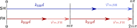
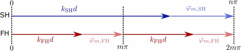
Figure 2 Cavity phase matching and double-resonance conditions. The vectors indicate the phases accumulated by the SH (top line) and FH (lower line) over half a round-trip in the cavity. We distinguish between the phases accumulated along the propagation in the cavity,  , and the phases gained upon reflection by the mirror,
  . Phase-matching occurs when the mirror phase-mismatch compensates for the propagation phase-mismatch. Being resonant modes in the cavity, these phases amount to integer multiples of π, such that
  .
.
Download figure:
Standard image High-resolution imageTo fulfill conditions (17) and (18) we follow the recipe proposed by Berger et al in [26], for enhancing second-harmonic generation (SHG) in a semiconducting vertical cavity:
1
One coherence length propagation: , where
  (i = FH, SH) is the wave-vector of the harmonics in the direction perpendicular to the cavity plane, and LLN is the LiNbO
 slab thickness (for our example wavelengths this is about 10 µm).
2
Rephasing upon reflection: , with q an odd integer. In other words, the two harmonics are rephased after every pass through the cavity by the reflection phases of the DBR mirrors
  , (i = FH, SH).
These cavity phase-matching conditions thus ensure that energy flows continually from the SH to the FH throughout the multiple cavity round-trips.
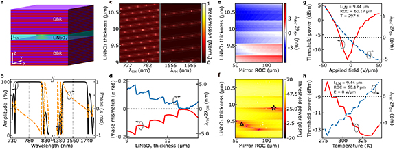
Through the proper design of the dielectric layers they are made of, DBRs offer the freedom to tailor both their reflection amplitude and phase profiles, to aid in the device performance. In particular, layer designs such as in references [26, 27] create two stop-bands, efficiently reflecting both the SH and the FH waves (lowering out-coupling losses) with the correct phases for phase-matching the cavity. Focusing on the micro-cavity design depicted in figure 3(a), we show in figure 3(b) the simulated reflection spectrum of such a dual stop-band DBR made of alternating layers of SiO2 and Ta2O5 (with average refractive indices of 1.45 [28, 29] and 2.1 [28, 30], respectively), interfacing LiNbO as the input medium, with refractive index based on Sellmeier and thermo-optic dependence [31]. This use of the bulk properties of LiNbO
 is justified by its relatively large thickness, necessary for the above phase-matching recipe. The large refractive index difference between SiO2 and Ta2O5 reduces the light penetration depth into these mirrors, contributing to stronger field confinement and interaction with the non-linear medium in the cavity. These materials also feature a very low absorption at the desired operating wavelength.
Figure 3 (a) Schematic of the VCOPO device. A slab of LiNbO is embedded between two dual-stop-band DBRs. (b) Simulated reflection spectrum (amplitude—black, phase—dashed orange) of a single DBR with two stop-bands around 780 nm and 1560 nm. The DBR phase response provides approximately π phase-mismatch between the two harmonics. (c) Simulated cavity transmission spectra around 780 nm (left) and around 1560 nm (right) as function of LiNbO
 thickness. (d) Simulated phase mismatch between the SH and FH fields along half a cavity roundtrip, and detuning from double resonance condition as function of the LiNbO
 thickness. (e), (f) Detuning from the double resonance condition (e) and estimated OPO threshold (f) as a function of the LiNbO
 thickness and mirror ROC at 297 K, for the fundamental transverse Gaussian mode. The pump is kept in resonance with the SH cavity mode. (g), (h) Detuning (dashed line) and OPO threshold (continuous line) as function of DC electric field applied across the LiNbO
 layer (g) and temperature (h). Cavity thickness: 9.44
  , mirror ROC: 60.17
  .
.
Download figure:
Standard image
Comments (0)